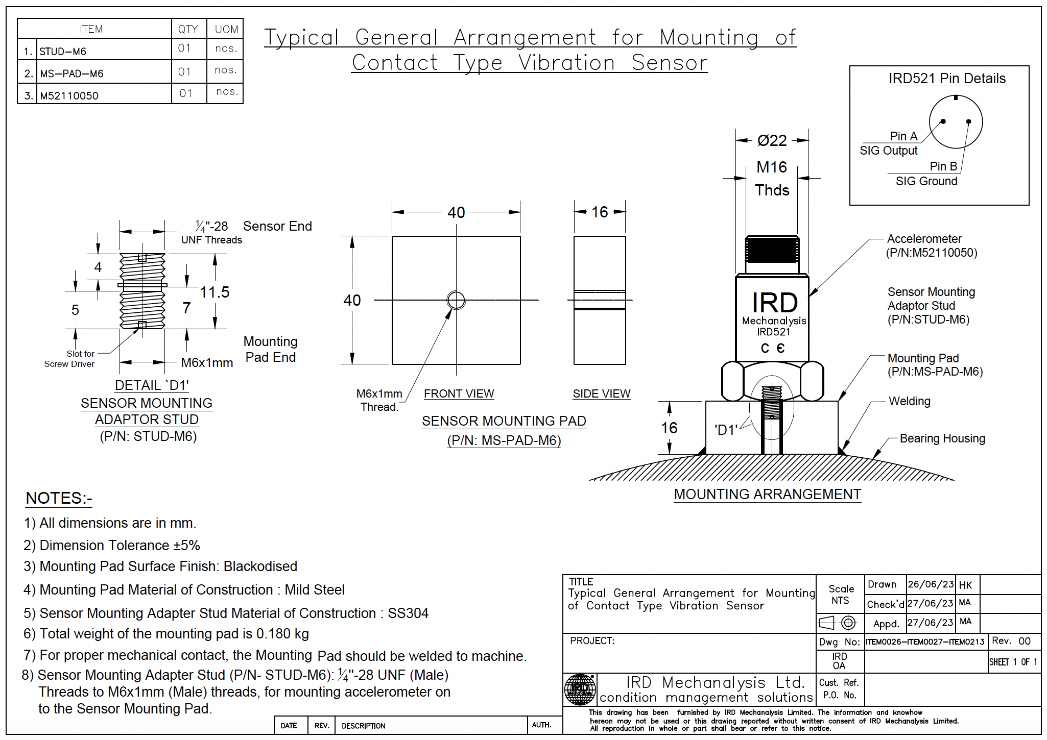
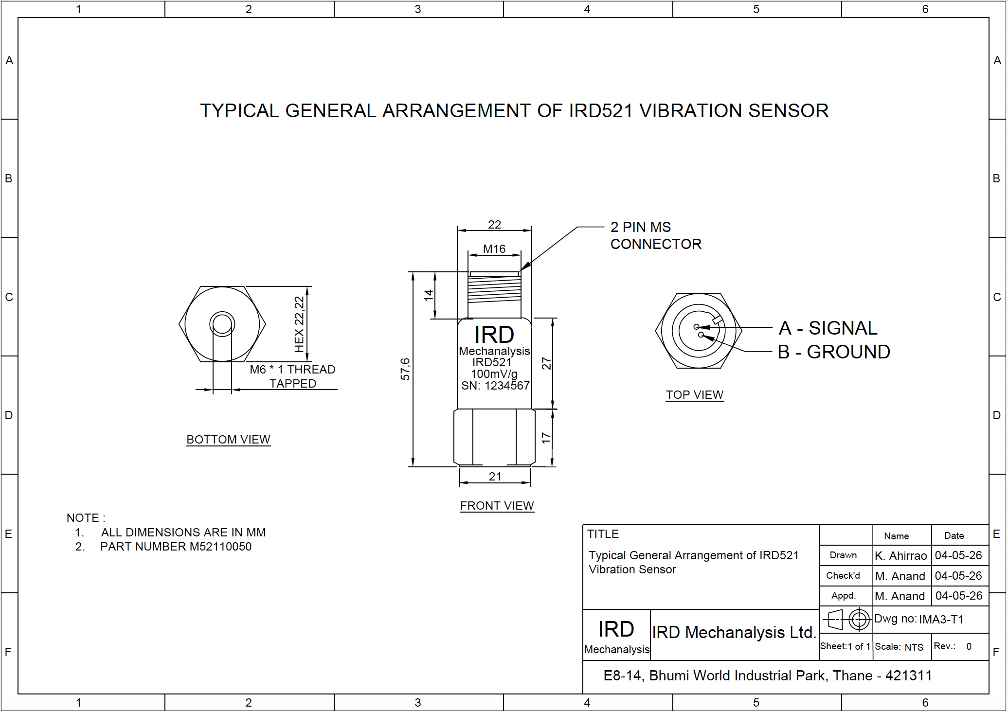
General Arrangement Drawing of IRD521 Vibration Sensor

General Arrangement Drawing of IRD521 Vibration Sensor

General Arrangement Drawing of IRD521 Vibration Sensor
Typical Mounting Drawing for IRD521 Vibration Sensor

    • Related Articles

    • Typical General Arrangement Drawings for IRD570 Sensor

      S No Drawing Title Link to Drawing PDF 1 General Arrangement Drawing of IRD570 Vibration Sensor with MS Mounting Pad 40 x 40 x 16 mm suitable for Stud M6 x 1 ITEM0026-ITEM0027-ITEM3596
    • User Manual of Generator End Winding Vibration Monitoring System Card M88280 of IRD8800 Series

      Attached to this Article is the User Manual of Generator End Winding Vibration Monitoring System (GEWVMS) Card M88280 of IRD8800 Series
    • How to check Calibration of IRD544 and IRD544M

      IRD544 and IRD544M are Inductive Type Velocity Output Vibration Sensors. They are used in both our Portable Instruments and Online Monitoring Systems. They provide a voltage output proportional to vibration velocity and the output which is also ...
    • Accuracy of Vibration Sensors

      Vibration Sensors have an output proportional to underlying vibration. This output is reported in terms of its sensitivity. When someone uses an accelerometer that has an output or sensitivity of 100 mV/g, this means that the sensor is providing a ...
    • How to connect a Loop Powered Vibration Sensor

      Loop Powered Sensors run on a DC Voltage Supply. They are a 2 wired system on which both supply is given and output is observed. Typically, loop powered sensors such as IRD591 are loop powered by DCS/PLC/SCADA by a 24 V DC supply. The sensor then ...